Electrical coupler for LEGO trains - Technical background
The Lego couplers
There are two different kinds of mechanical coupler in my Lego collection.
The old version from the 9V era uses a bigger magnet, than can spin around its mounting axle.
The newer version uses a smaller magnet within a full enclosure.
In this version, the magnet can move freely.
Both version share, that they don't differ between different sides of the vehicle.
Thus, both ends of a coach use the very same couplers.
Mounting the couplers on the coach is a bit different.
The newer version is part of a big buffer element.
The older version can be connected to a similiar buffer element, but can also be used without such element.
The coupler is connected via a half stud wide technic pin and thus can be mounted on a plate modified with technic holes as well as thin technic liftarms.
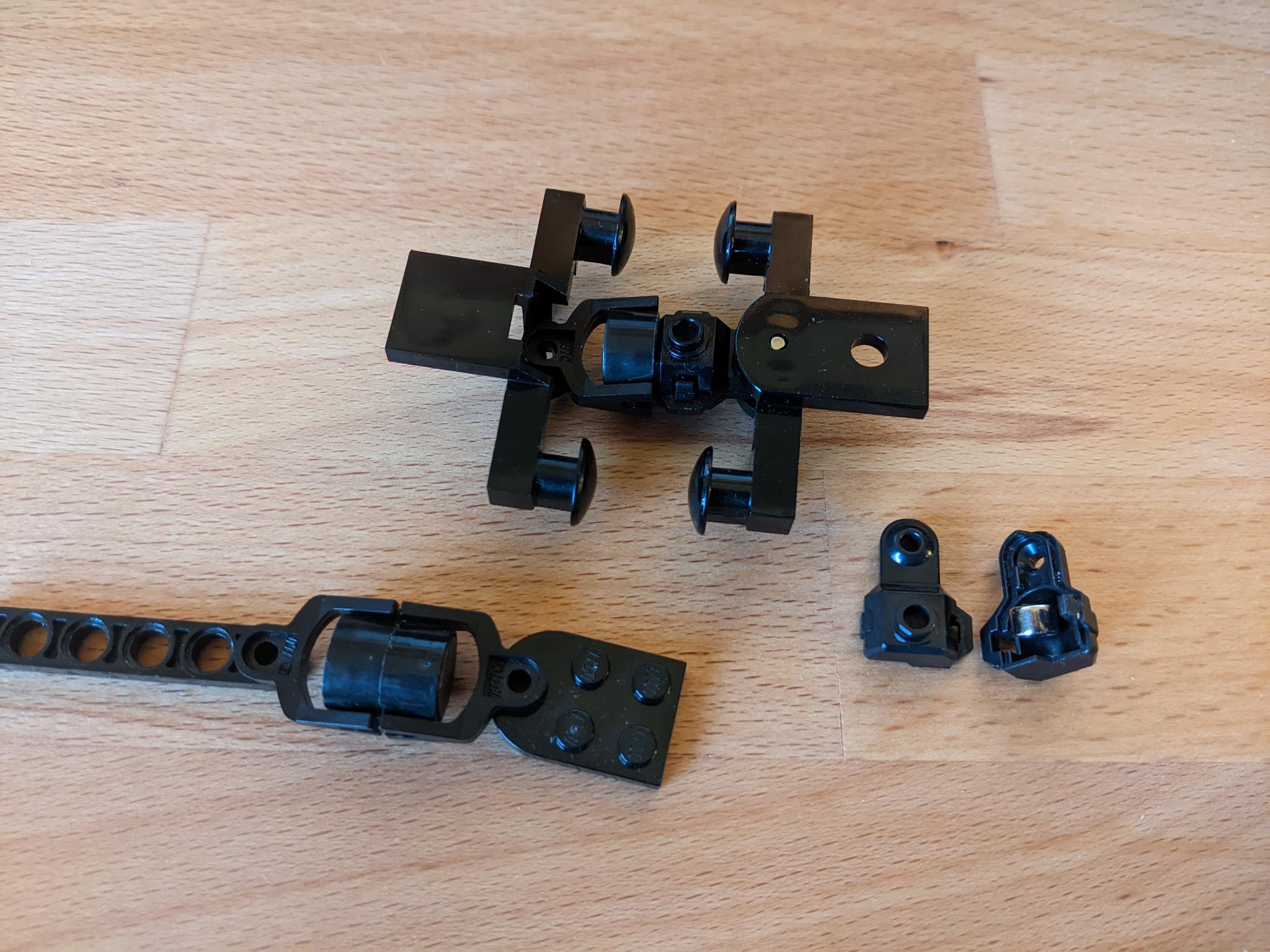 Both kinds of Lego train coupler in my collection
LEGO Power Functions
As the coupler is based on LEGO Power Functions, we have to understand these first.
Lego Power Functions uses a 4 wire cable, with two wires being reserved for power distribution and two wires being reserved for controlled application - eg. our traction.
The power distribution is on, als long as the battery box is on.
This is used to power the IR receiver.
Electrically speaking, this is really simple: one wire holds VCC = 9V, the other holds GND = 0V.
We can use it to power lights permanently.
The application wires C1 and C2 are only on, when controlled to be so.
Think of the IR receiver controlling a motor.
When used, one of the wires is linked to GND, while the other is linked to VCC.
Change of direction is achived by changing which wire is linked to VCC and GND and vice versa.
To adust the power output, PWM is used.
When not in use, or during an off duty PWM cycle, both wires are not connected to anything but air.
We can use these two wires for traction as well as lights that change with how fast or in which direction the train is traveling.
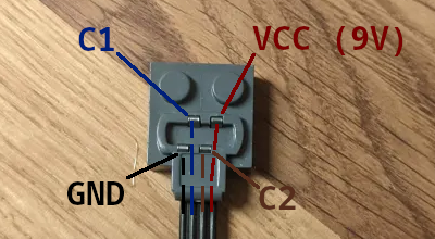 Pin assignment of a LEGO Power Functions connector
The direction of a Lego train motor
In the Lego universe, are powered coaches and or engines equipped with a train motor and a motor-dummy, which look (almost) the very same.
But there also are trains with asymetric boogies on the same powered coach / engine.
These tend to have the train motor on the rear side of the coach / engine.
Examples of this are almost all passenger trains I can think of, Lego produced in the past: Lego 4511, 7897, 7938, 60051, 60197, 60337...
So why does this matter?
These are exactly the kind of enige that features only one coupler.
And they have a clear driving direction.
The driving in the direction of the drivers cab equals driving forward.
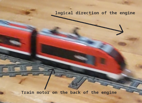 Logical direction of the Lego 7938 engine
To make things easy, this will be the reference for the placement of C1 and C2 in the coupler.
When C1 is on GND, and C2 is on 9V, the train will go forward.
Actual electrical couplers
On actual trains, the electrical coupler usually is a sperate entity attached to the mechanical coupler.
Often the electrical couplers can be moved by a piston, to either couple or de-couple.
This holds the advantage of the electrical coupler not having to coupler, when the mechanical coupler does and gets to use when the train is connected with another electrically not compatible train or loco.
A lid protects the electrical contacts when the coupler is de-coupled.
The connection between the electrical and the mechanical coupler is floating mounted allowing for a perfect alignment when being coupled.
Supporting the piston, a spring is used to keep coupled couplers locked. This ensures a high pressure between coupled electrical couplers.
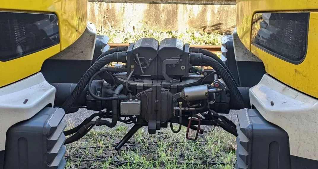 Coupled e-couplers on Stadler FLIRT 3
There have been attempts to simplify the complex design for the use on cargo wagons.
These designs came with a fixed electrical coupler and a lid that opens when connecting with another coupler.
This results in issues coupling with couplers that are not fully compatible.
Sadly they had issues with data connections breaking of during the field tests and thus the project moved to different designs.
Regardless, they still can be a source of inspiration.
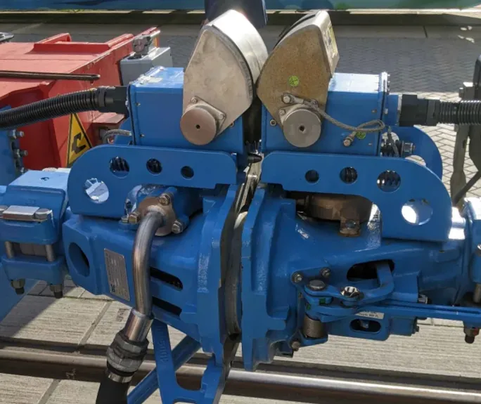 Real world e-coupler simplified for cargo wagons
Fixed- and spring loaded contacts
There are two different kinds of electrical contacts used in electrical couplers.
Typical designs are crown spring contacts and pogo pins.
Full scale examples of these can be found at:
male-female-contact-systems and
mobile-fixed-contact-systems.
Male-female-contact systems use crown spring contacts as female contacts.
Mobile-fixed-contact systems use pogo pins as mobile contacts and couple with a fixed plate of brass.
Crown spring contacts tend to be cheaper and simple in design.
Pogo pins have their advantage in compensation for play.
Them being able to compress allows for designs that can safely couple against an electrically insulated wall.
Crown spring contacts would crash in that scenario.
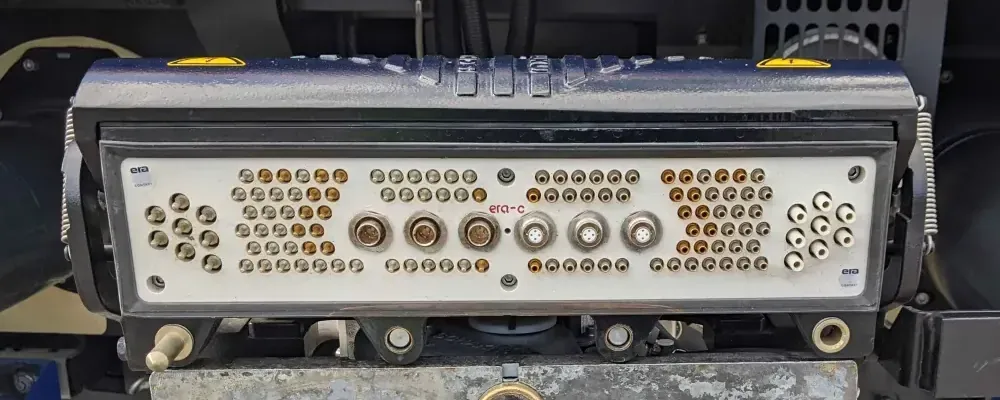 Real world e-coupler with open lid showing crown spring contacts
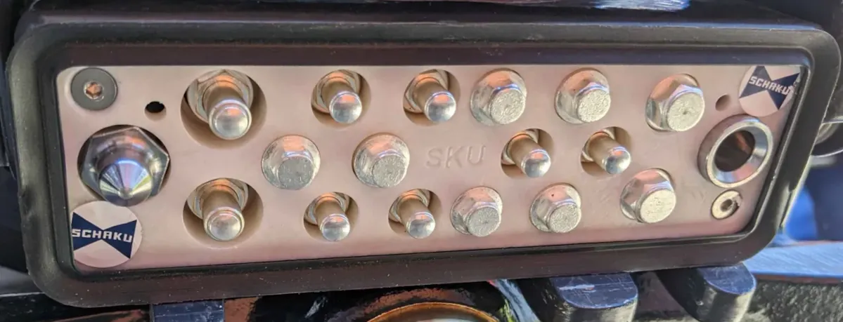 Real world e-coupler with open lid showing pogp pin contacts
Contact and Copyright:
webmaster@flemmbrav.de
latest change: happened
 Both kinds of Lego train coupler in my collection
 Pin assignment of a LEGO Power Functions connector
 Logical direction of the Lego 7938 engine
 Coupled e-couplers on Stadler FLIRT 3
 Real world e-coupler simplified for cargo wagons
 Real world e-coupler with open lid showing crown spring contacts
 Real world e-coupler with open lid showing pogp pin contacts