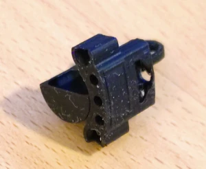
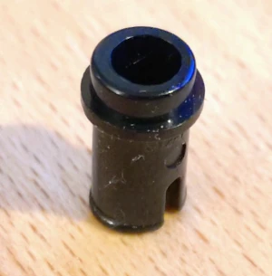
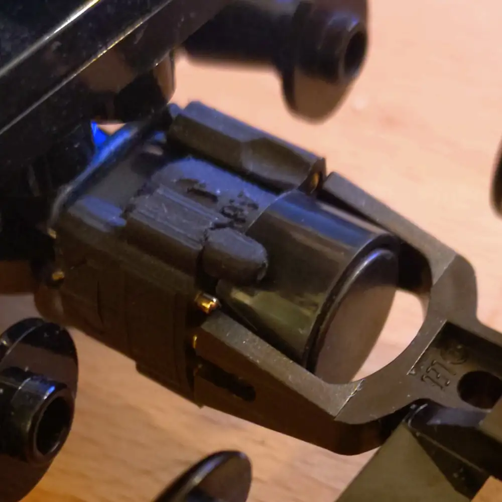
Electrical layout of the coupler
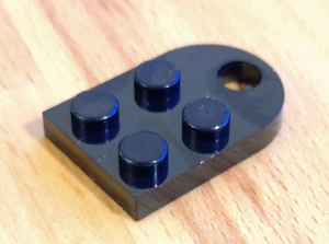
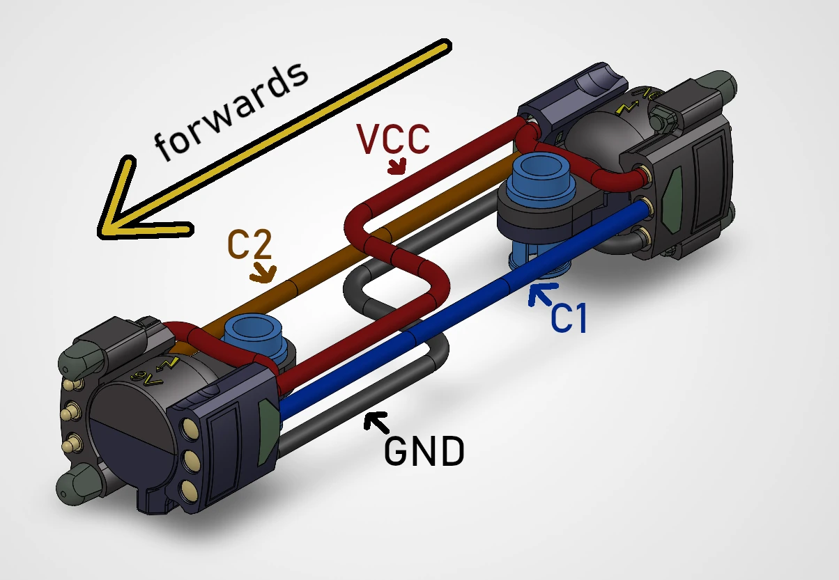 Pin assignment of the electrical coupler
So we have four wires, thus we need four contact pins on the electrical coupler?
No, not that easy.
If we did that, we would not be able to change the direction of travel of the individual vehicles in our train. To make this possible, we must ensure that the same cables are always connected to each other, even when the vehicle is travelling "backwards".
Thus, the pin layout on the coupler has to be symetrical.
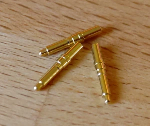
The spring loaded pin on the left hand side needs to connect to the same wire, as the fixed pin on the right hand side.
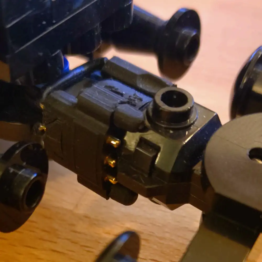
This is exactly, how the VCC and GND wires will be connected to the coupler.
The VCC wires will occupy the upper pair of contacts, while the GND wires will occupy the lower pair of contacts.
This way, they can not be mixed up by changing the direction of individual vehicles in the train.
However, the C1 and C2 wires are different.
In this special case, it actually fits quite well to have them switched around when changing the direction, the individual vehicle is traveling.
Thus, they are not placed symetrical.
Instead, they do not change place on the other end of the vehicle. One wire is on the left hand side of the vehicle, and the other is on the right hand side of the vehicle.
| Channel | Colour | Side | State when traveling forwards | State when traveling backwards |
|---|---|---|---|---|
| C1 | blue | left | GND | VCC |
| C2 | brown | right | VCC | GND |
When changing the direction of an individual vehicle, the C1 pin of the changed vehicle will connect to the C2 pin of the other vehicles, and vice versa. When the train moves forwards, the power in the changed vehicle will suggest it going backwards. Which is exactly what we want, as the "backwards" of the backwards facing vehicle equals forwards of the forwards facing train.
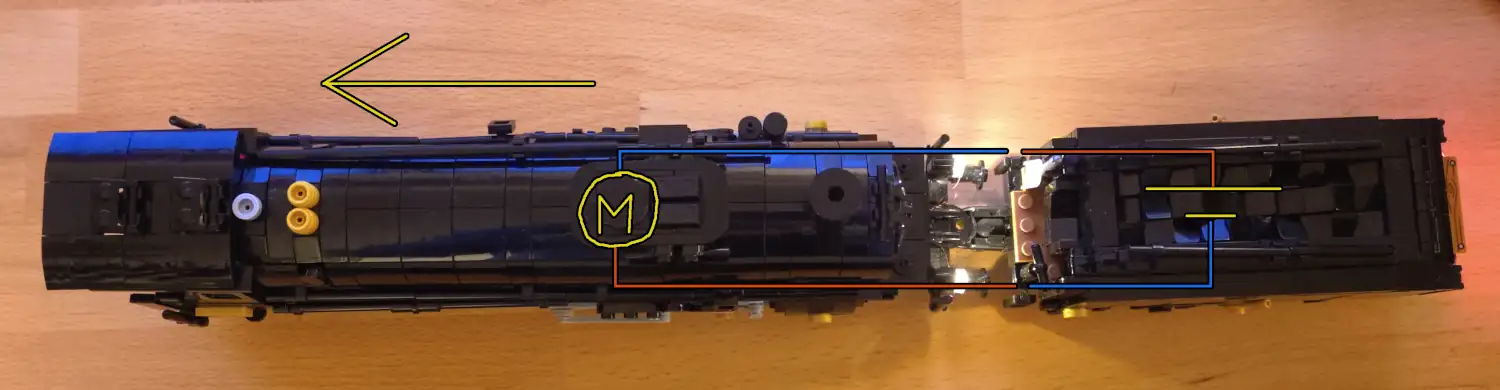
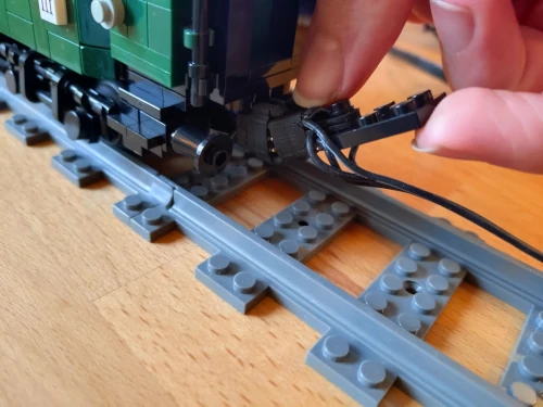
The next two pictures show the principle implemented on a steam engine. The tender holds the battery as well as the bluetooth receiver.
In the first picture, the back of the engine is coupled to the front of the tender. Both of them face in the same direction. The battery in the tender powers the motor wires.
On the tender, the brown wire is connected to VCC, the blue wire is connected to GND.
On the engine, the brown wire is connected to VCC, the blue wire is connected to GND. The motor makes the engine drive forwards compared to the natural direction of the engine, which is also the same as the direction of the tender holding the battery.
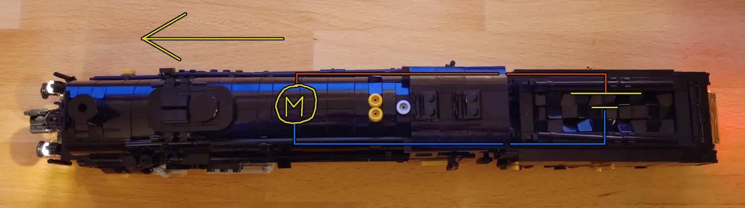 Schematics of a tender engine where the tender and the engine face in the same direction
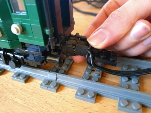
In the second picture, the front of the engine is coupled to the front of the tender.
Both of them face in the opposite direction.
The battery in the tender powers the motor wires.
On the tender, the brown wire is connected to VCC, the blue wire is connected to GND.
On the engine, the brown wire is connected to GND, the blue wire is connected to VCC.
The motor makes the engine drive backwards compared to the natural direction of the engine, which is the forward as the direction of the tender holding the battery.
 Schematics of a tender engine where the tender and the engine face in the opposite directions
As one can see, the train travels in the same direction both cases.
It's the direction the car holding the receiver (and in this case battery as well) is facing, which is the tender in this case.
This alignment ensures all engines travel in the very same direction.
It also ensures the train traveling in the direction, the remote control is dictating towards the receiver in the tender.
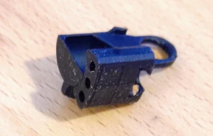
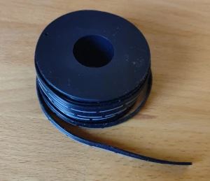
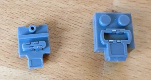
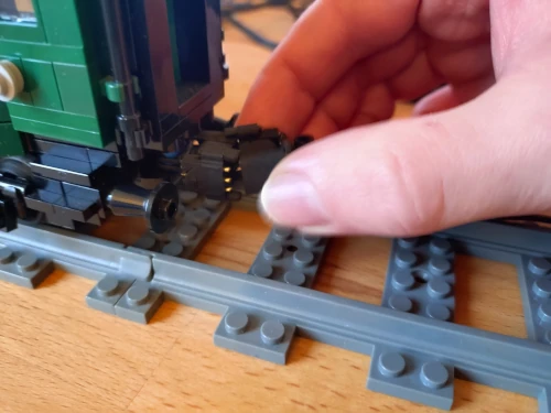
 Coupler with a flat ribbon cable
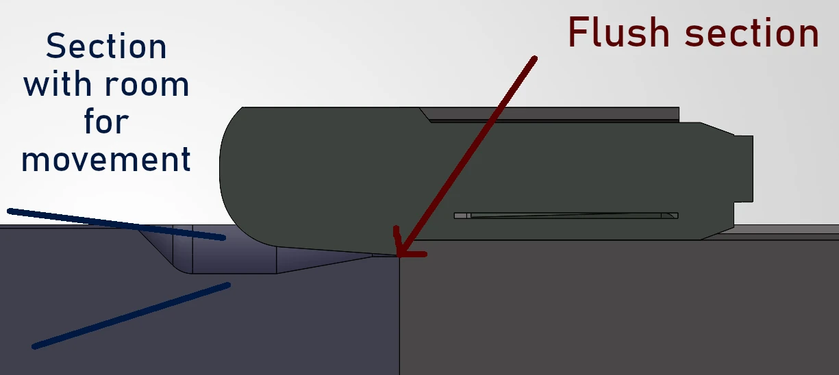
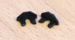
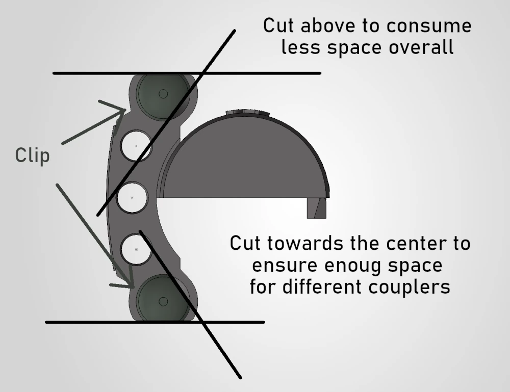 Geometry of the centering devices seen from the front of the coupler
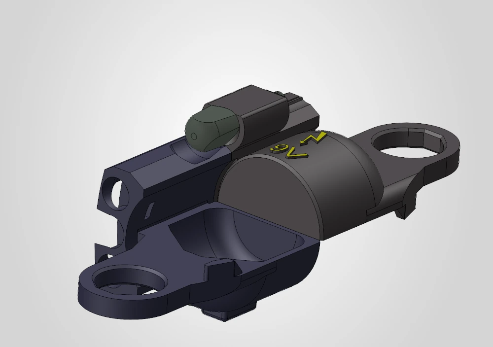
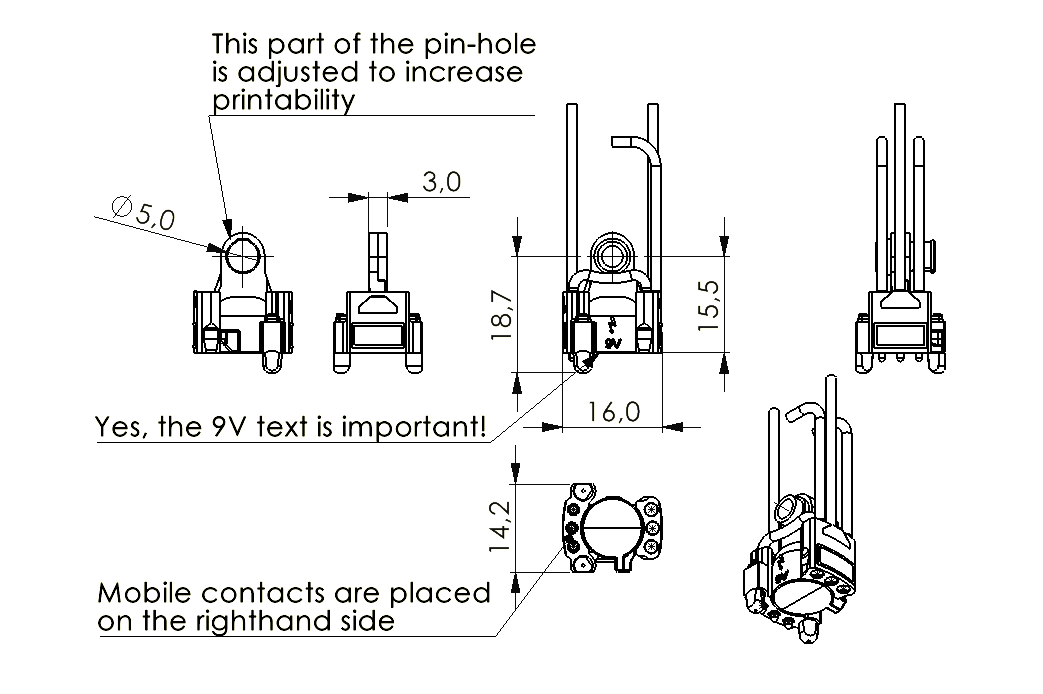 Drawing of the housing, dimensions in mm