Printing the housing
We start by printing the housing.
I use a bambulab A1 mini with a flat build plate as well as a 0,2 mm nozzle.
The layer heigth is set to 0,06 mm, material in use is PLA.
My printer takes around 1,3 g of PLA and 70 minutes to print the housing for a coupler.
Different print settings will likely work as well, but I did not test them.
The 0,2 mm nozzle does some heavy lifiting in terms of print quality, and I can not recommend using a bigger nozzle.
With that restriction, different materials might not be easy to print.
Printing this coupler in resin should work as well.
Allthough I did not test this with this specific design.
The clips on the centering devices might cause issues with very brittle material.
You might end up glueing them in when using a resin printer.
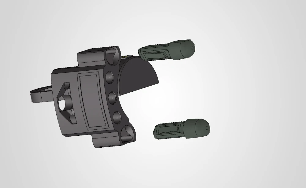
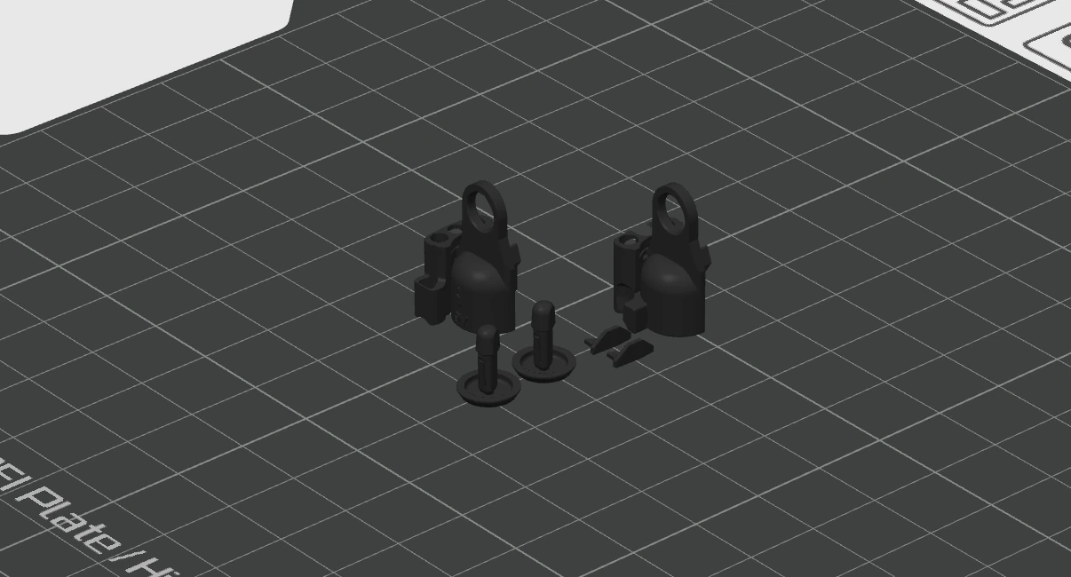 Step 1.1: Place the objects on the print bed as seen above
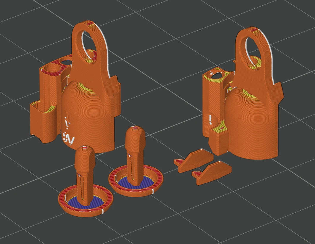 Step 1.2: Slice the files. You can see the small nozzle doing magic here. The thin walls work best when printing slow and fine
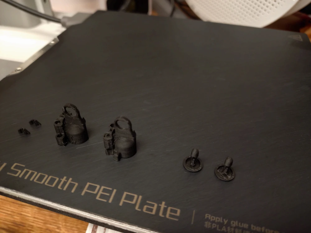 Step 1.3: The print job is done
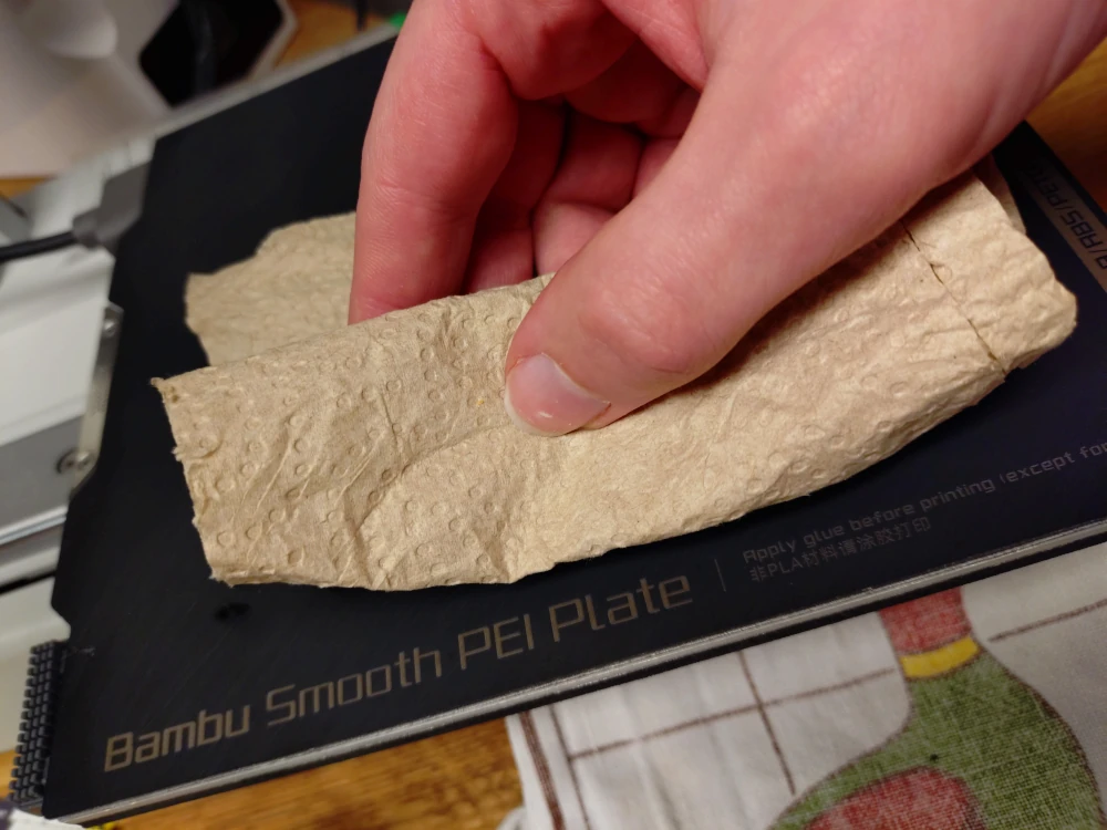
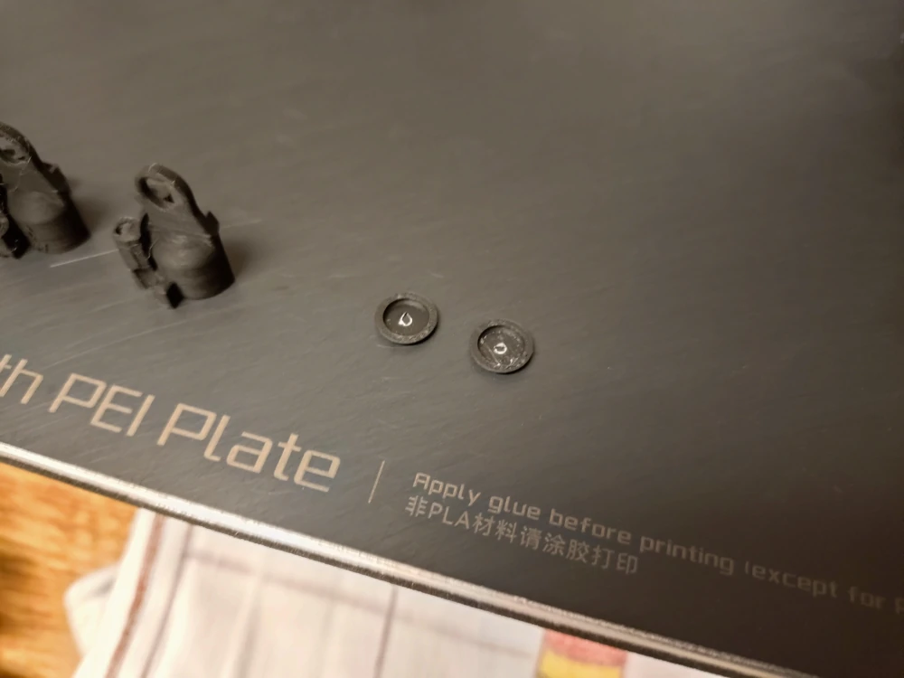 Step 1.4: Remove the centering devices from the rafts. I recommend using a paper towel to remove the parts, so you do not end up touching the build plate with your greasy hands
 Step 1.5: Remove the other four printed parts and the rafts
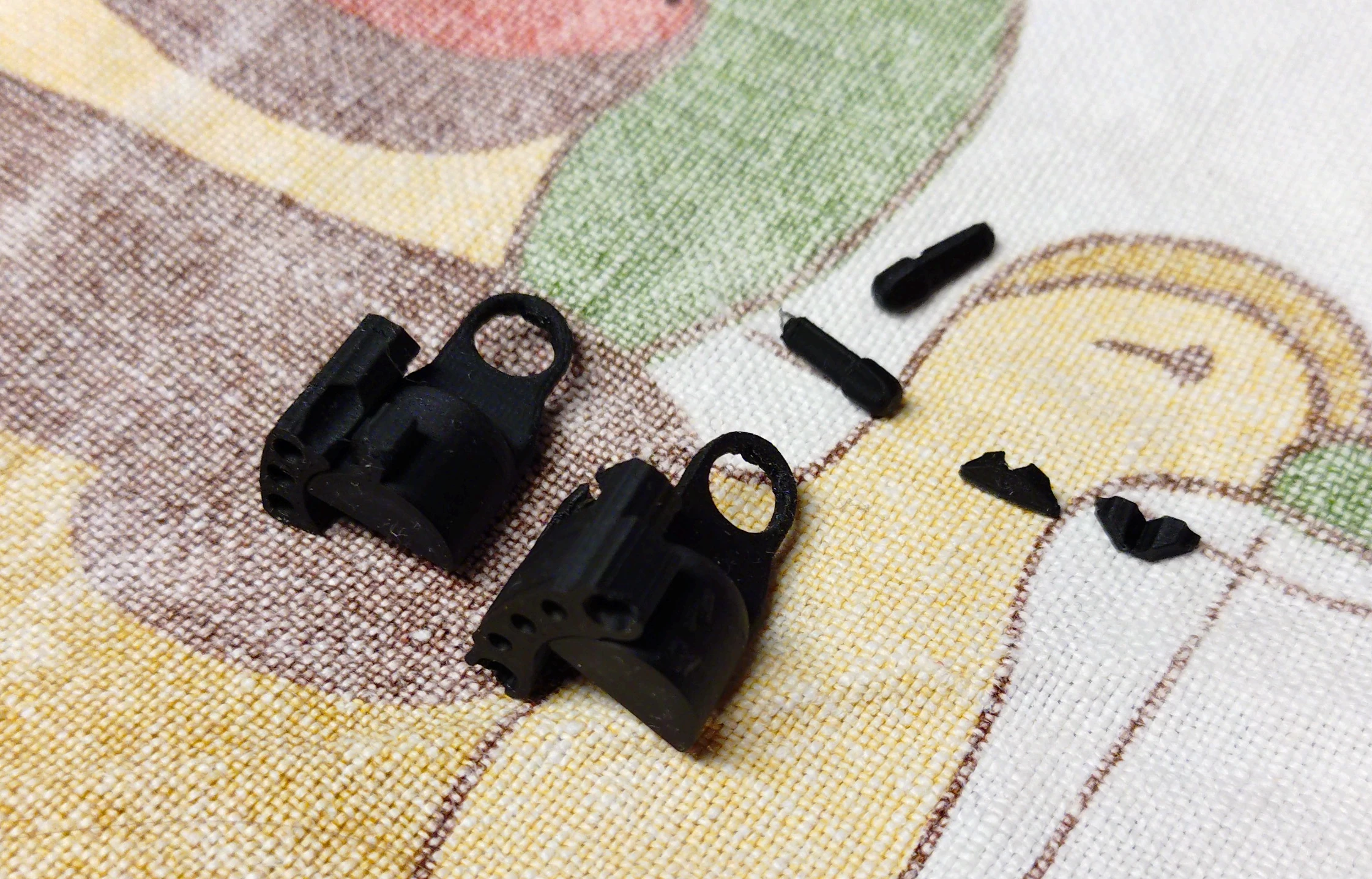 Step 1.6: Overview of the printed pieces
 Step 1.7: Clip the centering devices into the upper housing
 Step 1.8: All done! The housing can be put to the side for now.
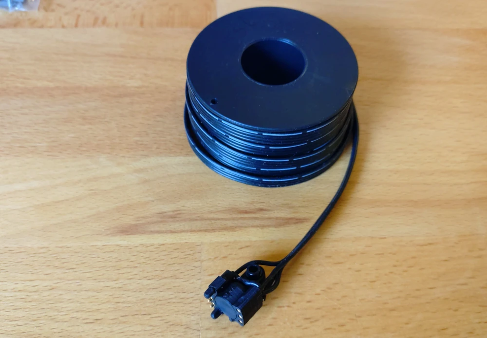
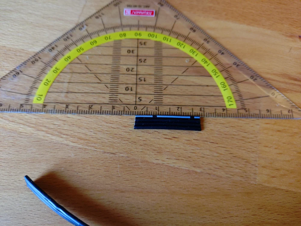 Step 2.1: Cut 25 to 28 mm from the cable.
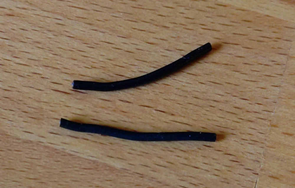 Step 2.2: And seperate two wires from that. We'll need these two to connect between both the VCC and GND connectors from one side to the other.
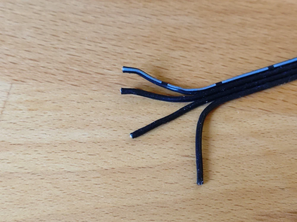 Step 2.3: In case you're using a flat ribbon cable, seperate the ends of the cable a bit to help working on it.
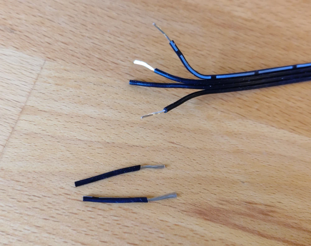 Step 2.4: Remove 7 to 9 mm of insulation from the two short wires as well as VCC, GND and the C-wire that you want to have on the fixed side for this very coupler.
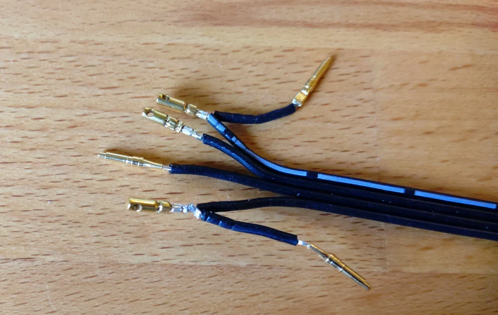
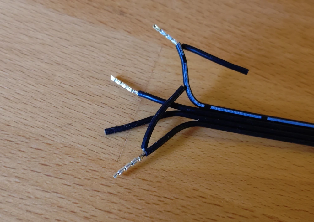 Step 2.5: Crimp the wire end ferrules on the wires.
The C1/C2 wire will have their own wire end ferrule.
The VCC and GND wires will share the wire end ferrules with their extra cable that connects to the other side of the coupler.
Step 2.5: Crimp the wire end ferrules on the wires.
The C1/C2 wire will have their own wire end ferrule.
The VCC and GND wires will share the wire end ferrules with their extra cable that connects to the other side of the coupler.
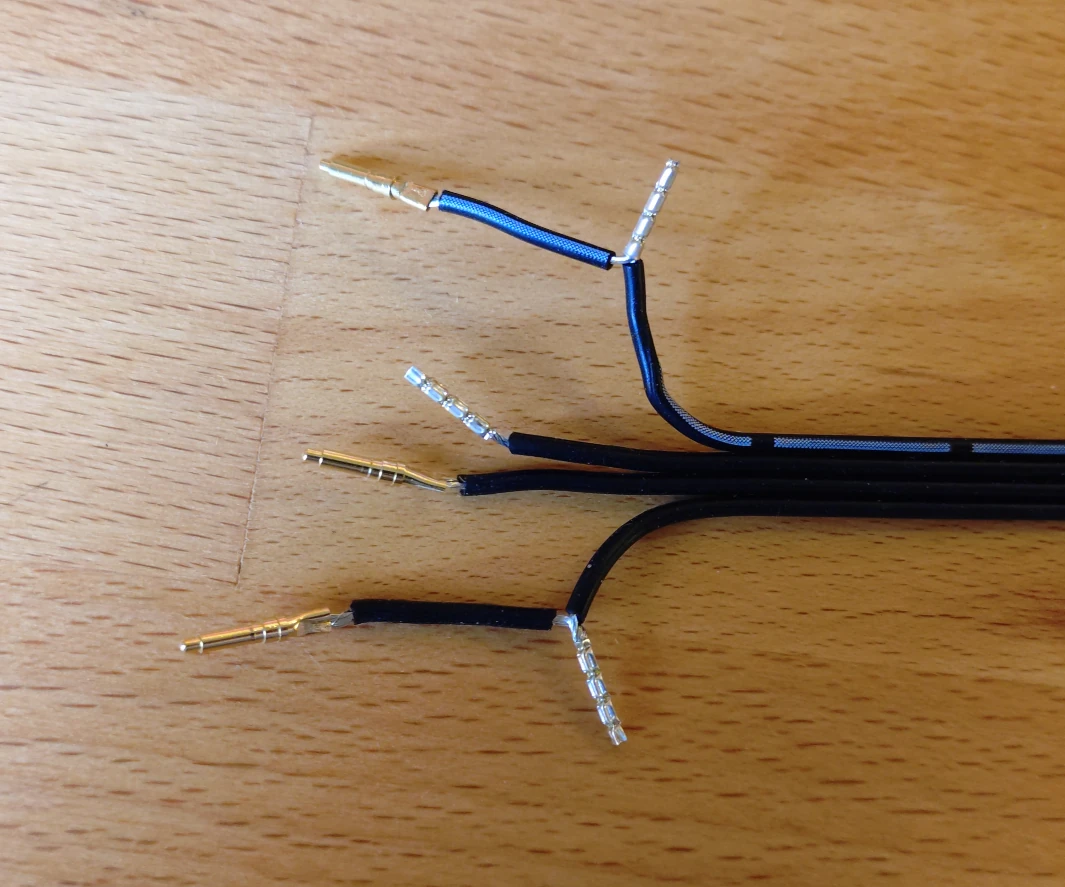 Step 2.6: Remove 5 to 7 mm of insulation from all the other wires and crimp the pogo pins to the wire.
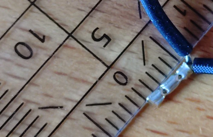 Step 2.7: Shorten the wire end ferrules to 5 mm length.
 Step 2.8: Crimp the steel cord capes on the wire end ferrules.
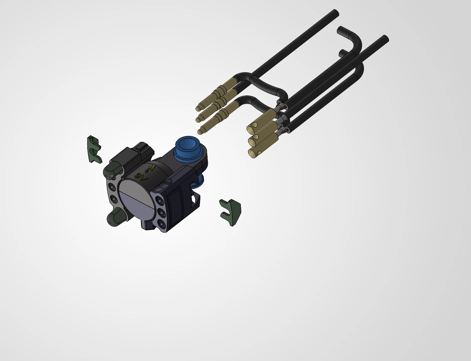
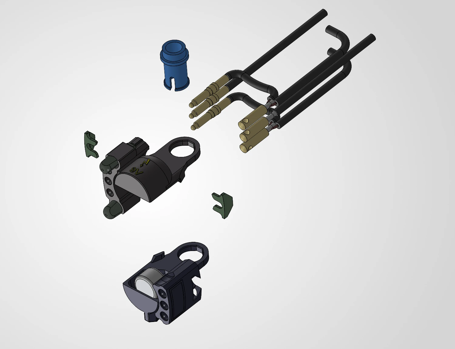 Step 3.1: Prepare the housing and the wire harness.
 Step 3.2: Clip both parts of the housing together and secure it with the technic pin 4274.
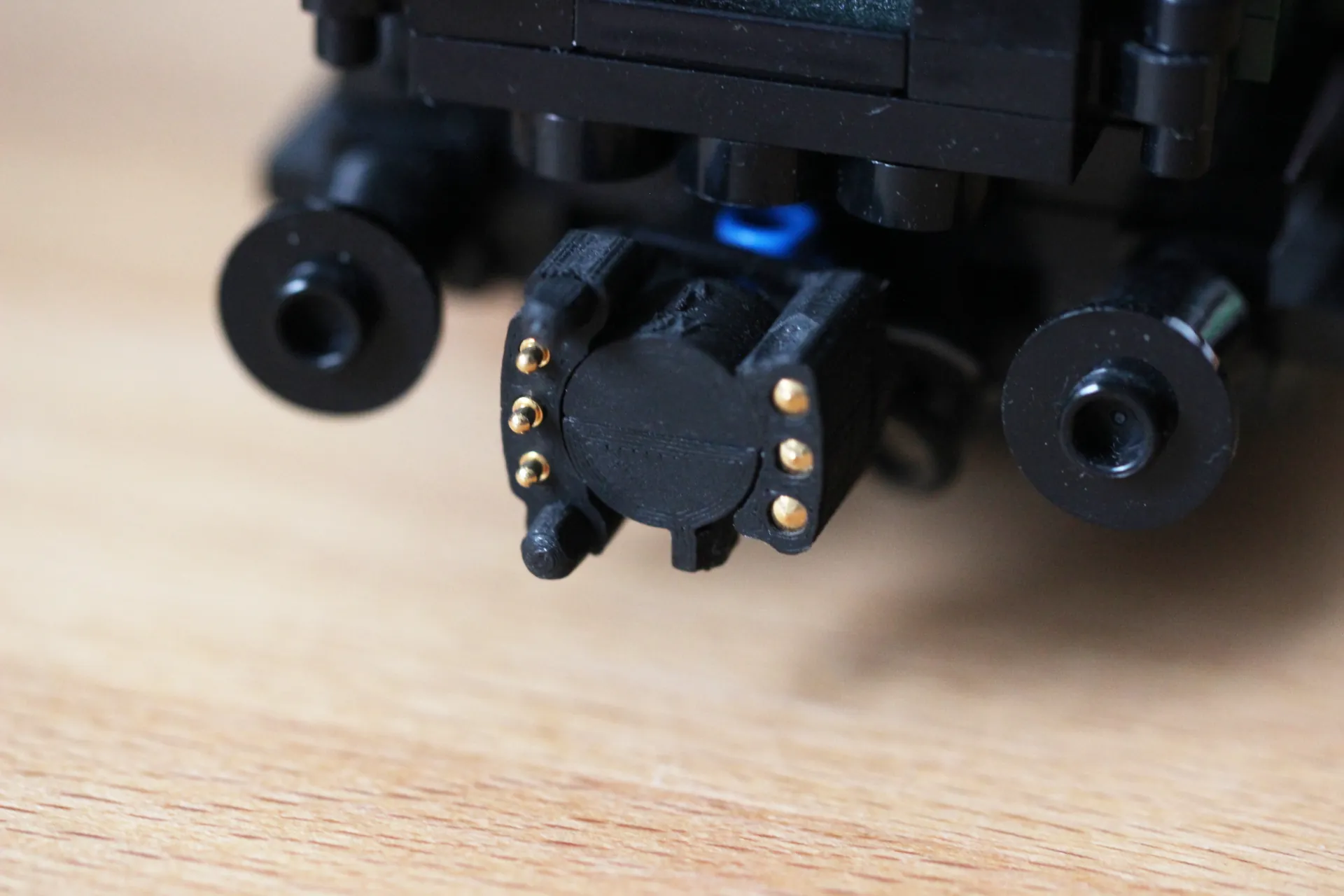
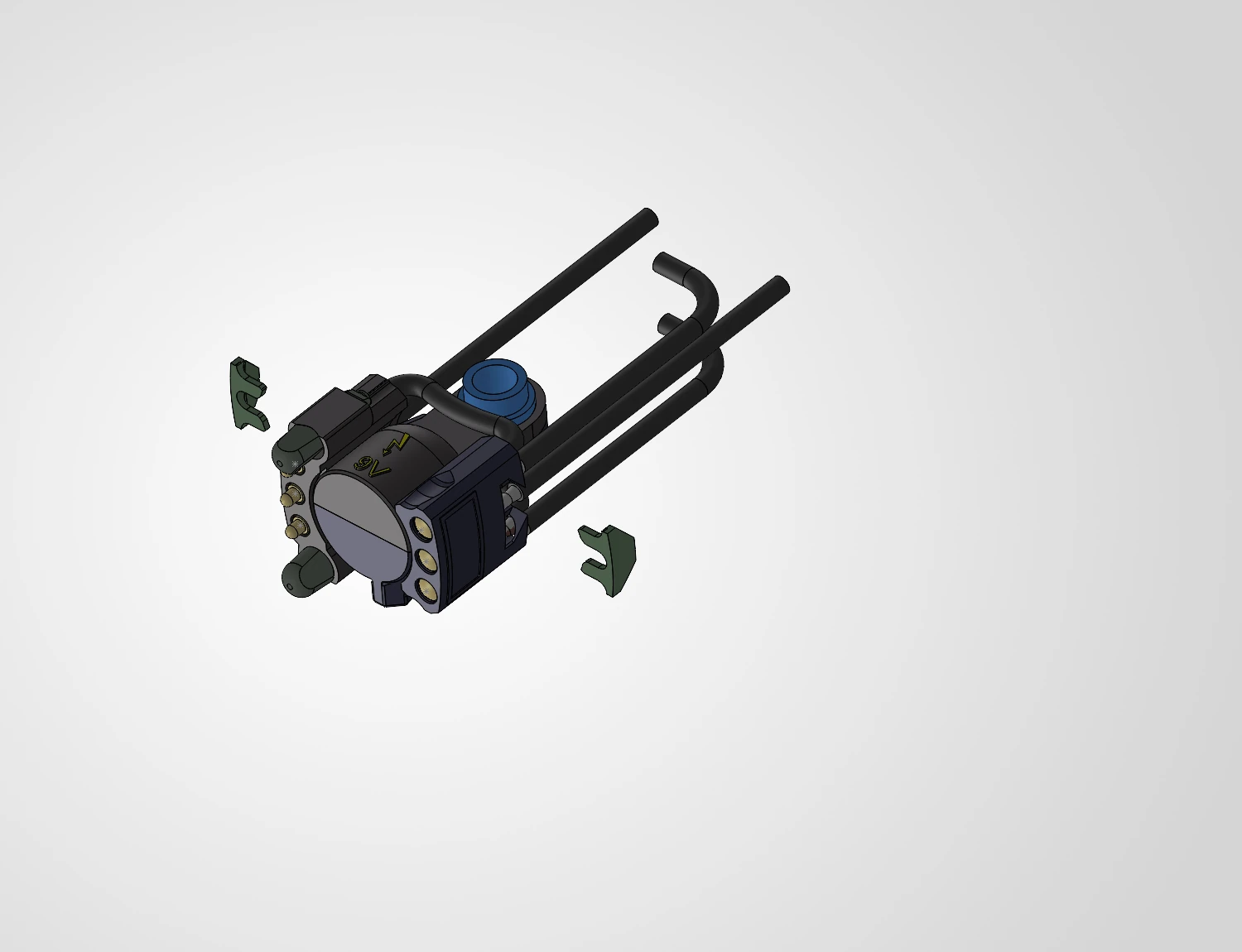 Step 3.3: Push the contacts into the housing.
Starting with the pogo pins works best for me, but there is no fixed order.
Step 3.3: Push the contacts into the housing.
Starting with the pogo pins works best for me, but there is no fixed order.
 Step 3.4: Push the clips in from the side to secure the wire harness to the housing.
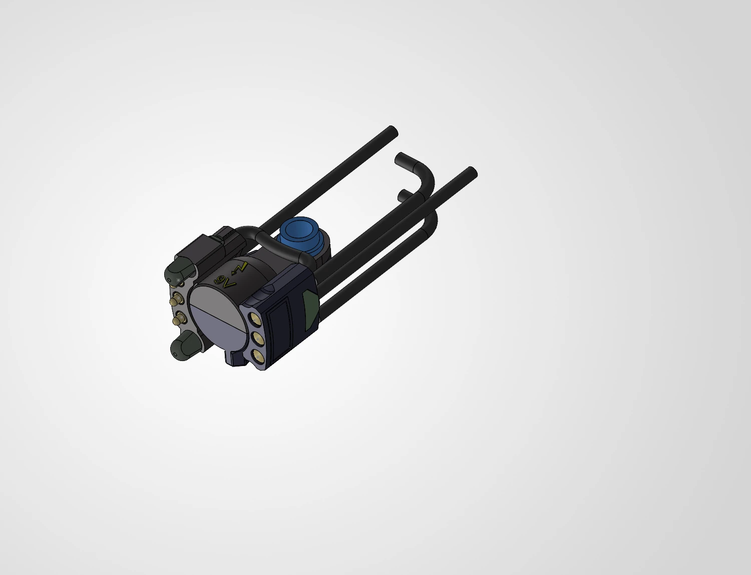
 Step 3.5: All done! At least for the coupler.
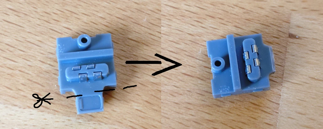 Step 4.1: Cut the housing on the connector.
This seems weird, I'm well aware.
But we're using larger wires than the connector is designed for.
If we would not do this, the connector would not be able to close fully, and thus would be bigger than two plates.
Step 4.1: Cut the housing on the connector.
This seems weird, I'm well aware.
But we're using larger wires than the connector is designed for.
If we would not do this, the connector would not be able to close fully, and thus would be bigger than two plates.
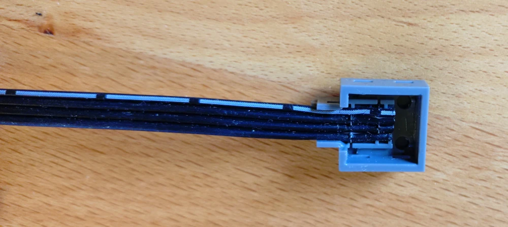 Step 4.2: Place to cable into the upper part of the connector.
Make sure of the clips only cutting the intended wire.
Step 4.2: Place to cable into the upper part of the connector.
Make sure of the clips only cutting the intended wire.
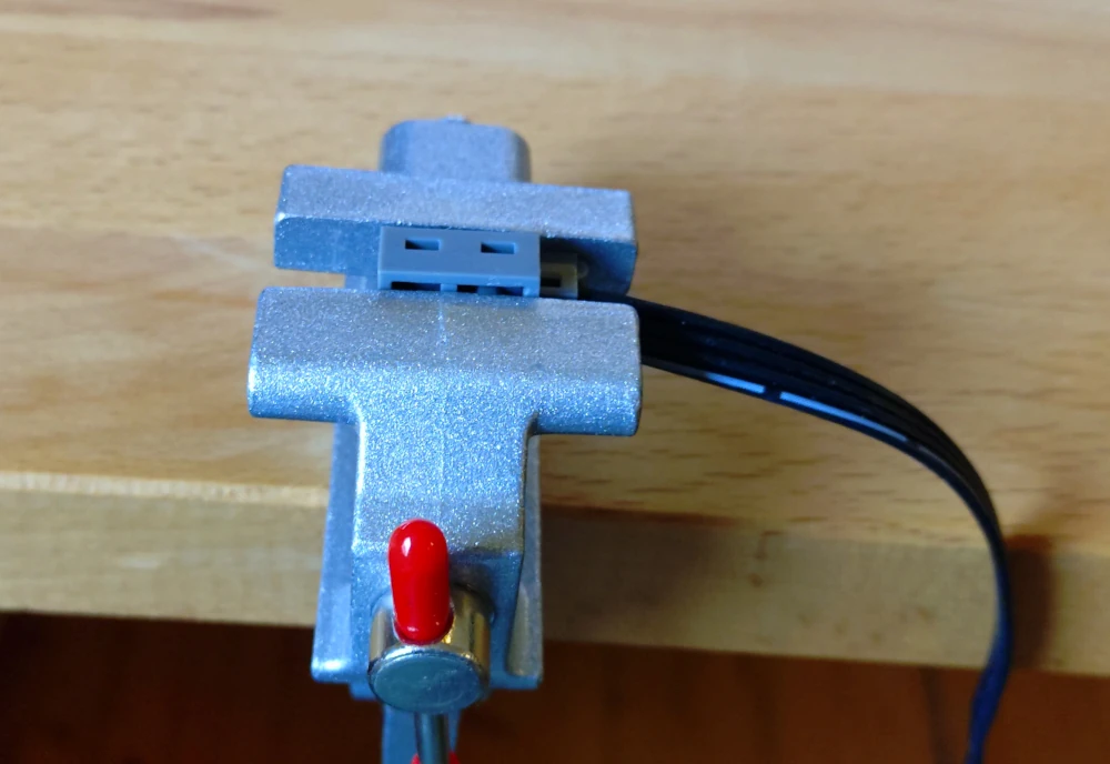 Step 4.3: Close the connector.
Mine need some extra help in that regard.
Step 4.3: Close the connector.
Mine need some extra help in that regard.
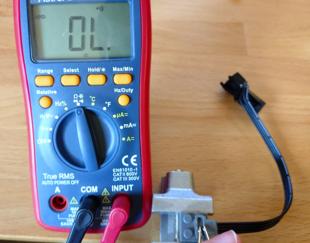 Step 5: Check the insulation as well as connections of the whole cable
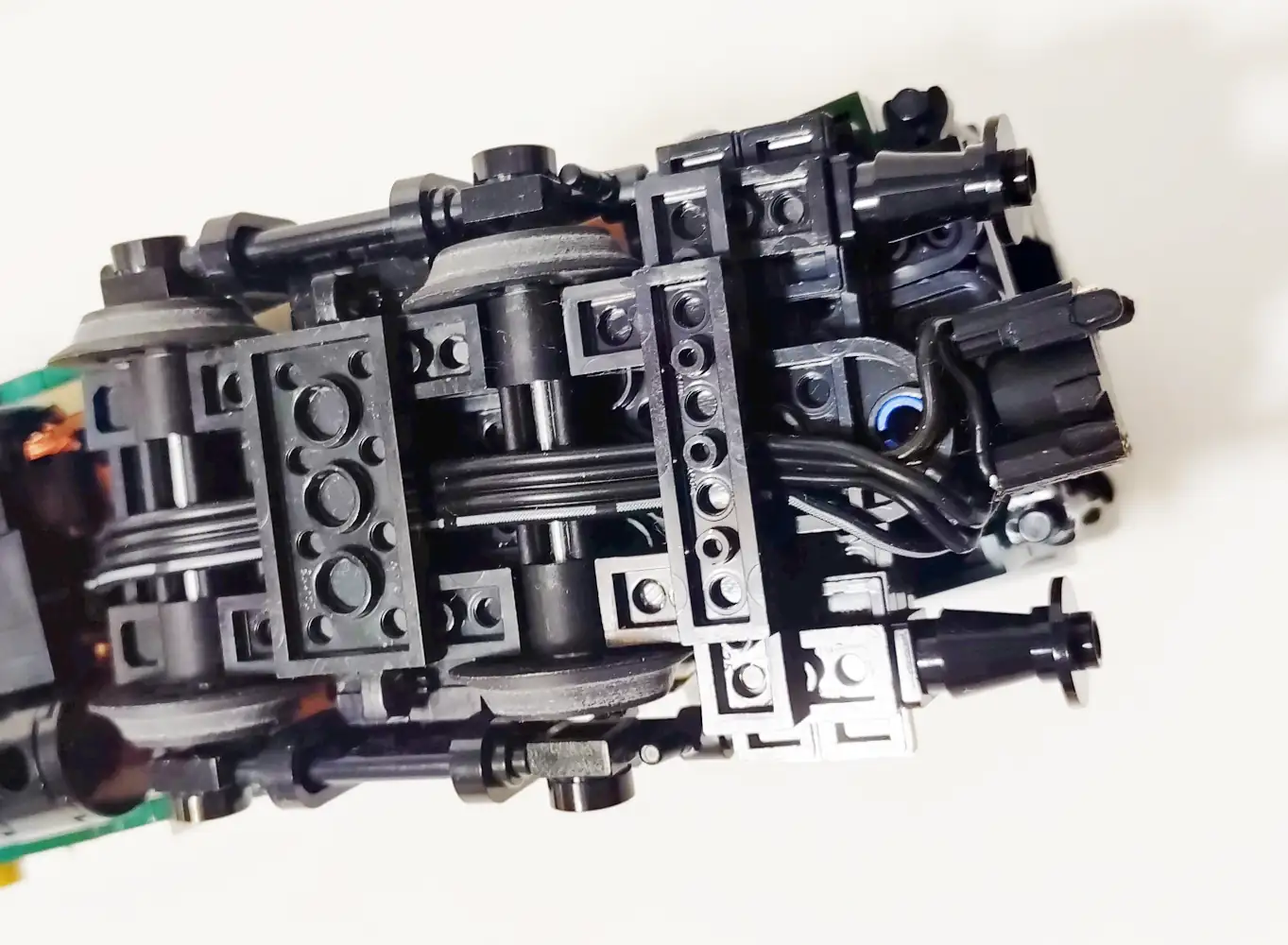
 Step 22: mount the coupler to your loco / tender / wagon / coach.
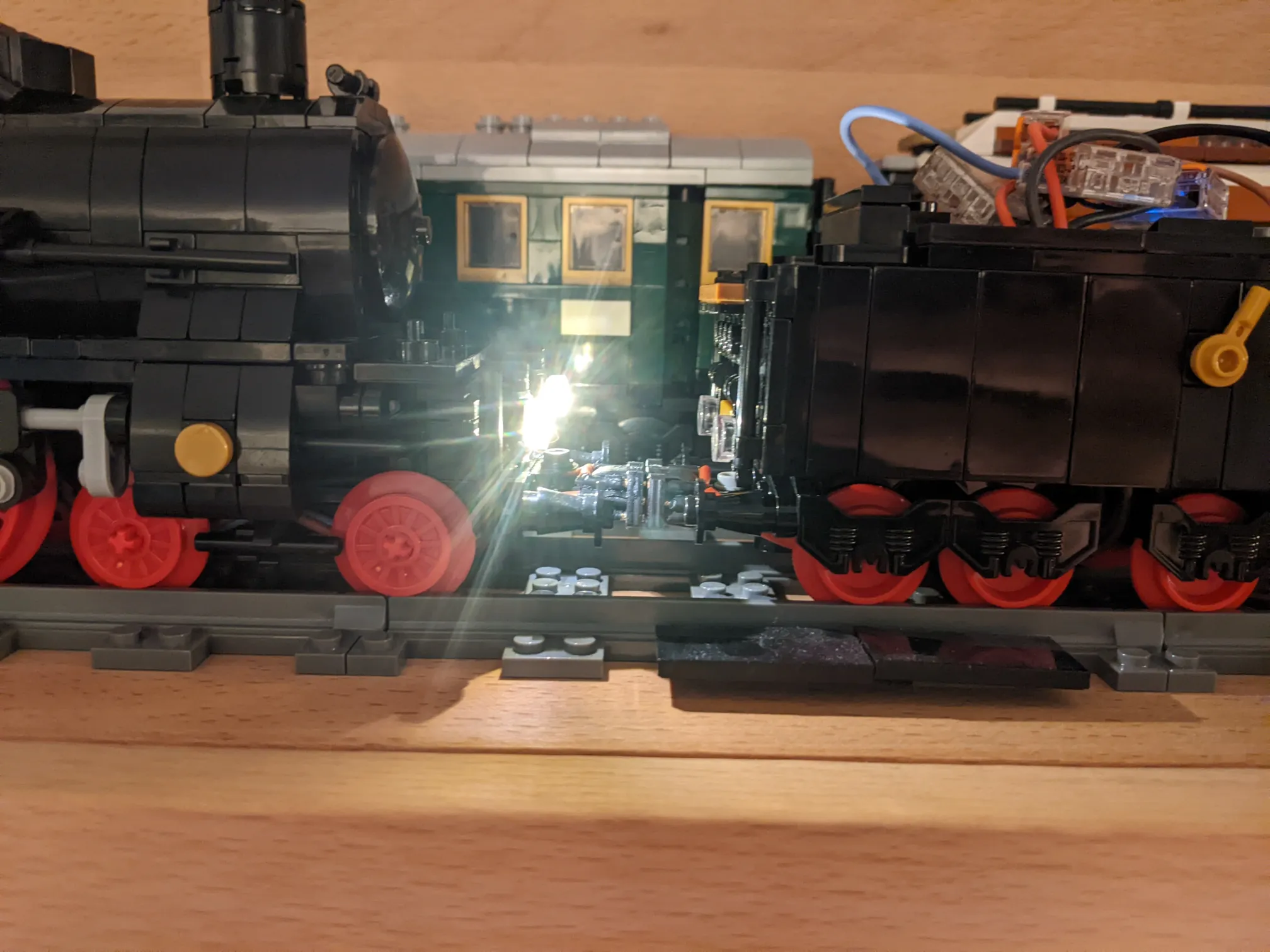 Step 23: have fun with the coupler!